
Key Turbocharger components and installation
Key Turbocharger components and installation
The turbocharger has three main components:
- A?turbine, which is almost always a?radial inflow turbine
- A compressor, which is almost always a?centrifugal compressor
- The center housing/hub rotating assembly (CHRA).
The first two components are the primary flow path components. Depending upon the exact installation and application, numerous other parts, features and controls may be required. ?


Center housing rotating assembly (CHRA)
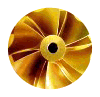
Compressor
- Impeller/diffuser/volute housing
- Ported shroud/map width enhancement
The flow range of a turbocharger compressor can also be increased by allowing air to bleed from a ring of holes or a circular groove around the compressor at a point slightly downstream of the compressor inlet (but far nearer to the inlet than to the outlet). The ported shroud is a performance enhancement that allows the compressor to operate at significantly lower flows. It achieves this by forcing a simulation of impeller stall to occur continuously. Allowing some air to escape at this location inhibits the onset of surge and widens the?compressor map. While peak efficiencies decrease, areas of high efficiency may notably increase in size. Increases in compressor efficiency result in slightly cooler (more dense) intake air, which improves power. In contrast to compressor exhaust blow off valves, which are electronically controlled, this is a passive structure that is constantly open. The ability of the compressor to accommodate high mass flows (high boost at low rpm) may also be increased marginally (because near choke conditions the compressor draws air inward through the bleed path). This technology is widely used by turbocharger manufacturers such as Honeywell Turbo Technologies, Cummins Turbo Technologies, and GReddy. When implemented appropriately, it has a reasonable impact on compressor map width while having little effect on the maximum efficiency island.
- Charge air cooler/Intercooler

Illustration of inter-cooler location.
For all practical situations, the act of compressing air increases the air’s temperature along with pressure. This temperature increase can cause a number of problems when not expected or when installing a turbocharger on an engine not designed for forced induction. Excessive charge air temperature can lead to?detonation, which is extremely destructive to engines. When a turbocharger is installed on an engine, it is common practice to fit the engine with an?intercooler?(also known as a?charge air cooler, or CAC), a type of?heat exchanger?that gives up heat energy in the charge to the ambient air. To assure the intercooler’s performance, it is common practice to leak test the intercooler during routine service, particularly in trucks where a leaking intercooler can result in a 20% reduction in fuel economy.
- Fuel-air mixture ratio
In addition to the use of intercoolers, it is common practice to introduce extra fuel into the charge for the sole purpose of cooling. The amount of extra fuel varies, but typically reduces the air-fuel ratio to between 11 and 13, instead of the stoichiometric 14.7 (in gasoline engines). The extra fuel is not burned, as there is insufficient oxygen to complete the chemical reaction, and instead undergoes a phase change from vapor (liquid) to gas. This reaction absorbs heat (the latent heat of vaporization), and the added mass of the extra fuel reduces the average kinetic energy of the charge and exhaust gas. The gaseous hydrocarbons generated are?oxidized?to carbon dioxide, carbon monoxide, and water in the catalytic converter. A method of coping with this problem is in one of several ways. The most common one is to add an?intercooler?or aftercooler somewhere in the air stream between the compressor outlet of the turbocharger and the engine intake manifold. Intercoolers and aftercoolers are types of?heat exchangers?that allow the compressed air to give up some of its heat energy to the ambient air. In the past, some aircraft featured?anti-detonant injection?for takeoff and climb phases of flight, which performs the function of cooling the fuel/air charge before it reaches the cylinders. In contrast, modern turbocharged aircraft usually forgo any kind of temperature compensation, because the turbochargers are in general small and the manifold pressures created by the turbocharger are not very high. Thus, the added weight, cost, and complexity of a charge cooling system are considered to be unnecessary penalties. In those cases, the turbocharger is limited by the temperature at the compressor outlet, and the turbocharger and its controls are designed to prevent a large enough temperature rise to cause detonation. Even so, in many cases the engines are designed to run rich in order to use the evaporating fuel for charge cooling.
Turbine
The housings fitted around the compressor impeller and turbine collect and direct the gas flow through the wheels as they spin at extremely high speeds of up to 250,000 rpm. The size and shape can dictate some performance characteristics of the overall turbocharger. Often the same basic turbocharger assembly will be available from the manufacturer with multiple housing choices for the turbine and sometimes the compressor cover as well. This allows the designer of the engine system to tailor the compromises between performance, response, and efficiency to application or preference. Twin-scroll designs have two valve-operated exhaust gas inlets, a smaller sharper angled one for quick response and a larger less angled one for peak performance. The turbine and impeller wheel sizes also dictate the amount of air or exhaust that can be flowed through the system, and the relative efficiency at which they operate. In general, the larger the turbine wheel and compressor wheel the larger the flow capacity. Measurements and shapes can vary, as well as curvature and number of blades on the wheels.?Variable geometry turbochargers?are further developments of these ideas. The center hub rotating assembly (CHRA) houses the shaft that connects the compressor impeller and turbine. It also must contain a bearing system to suspend the shaft, allowing it to rotate at very high speed with minimal friction. For instance, in automotive applications the CHRA typically uses a thrust bearing or ball bearing lubricated by a constant supply of pressurized engine oil. The CHRA may also be considered “water-cooled” by having an entry and exit point for engine coolant to be cycled. Water-cooled models allow engine coolant to be used to keep the lubricating oil cooler, avoiding possible oil?coking?(the destructive distillation of the engine oil) from the extreme heat found in the turbine. The development of air-foil bearings?has removed this risk. Adaptation of turbochargers on naturally aspirated internal combustion engines, on either petrol or diesel, can yield power increases of 30% to 40%.
- Variable geometry

Garrett?variable-geometry turbocharger on DV6TED4 engine
Instead of using two turbochargers in different sizes, some engines use a single turbocharger, called?variable-geometry or variable-nozzle turbos; these turbos use a set of vanes in the exhaust housing to maintain a constant gas velocity across the turbine, the same kind of control as used on power plant turbines. Such turbochargers have minimal lag like a small conventional turbocharger and can achieve full boost as low as 1,500 engine rpm, yet remain efficient as a large conventional turbocharger at higher engine speeds. In many setups, these turbos do not use a wastegate. The vanes are controlled by a membrane identical to the one on a wastegate, but the mechanism operates the variable vane system instead. These variable turbochargers are commonly used in diesel engines.
Wastegate

View of a turbocharger from the turbine exhaust side, showing the integral wastegate to the right
To manage the pressure of the air coming from the compressor (known as the “upper-deck air pressure”), the engine’s exhaust gas flow is regulated before it enters the turbine with awastegate?that bypasses excess exhaust gas entering the turbocharger’s turbine.?A?wastegate?is the most common mechanical speed control system, and is often further augmented by an electronic or manual?boost controller. The main function of a wastegate is to allow some of the exhaust to bypass the turbine when the set intake pressure is achieved. This regulates the rotational speed of the turbine and thus the output of the compressor. The wastegate is opened and closed by the compressed air from the turbo and can be raised by using a?solenoid?to regulate the pressure fed to the wastegate membrane.?This solenoid can be controlled by?Automatic Performance Control, the engine’selectronic control unit?or a boost control computer. Most modern automotive engines have wastegates that are internal to the turbocharger, although some earlier engines (such as the?Audi?Inline-5 in the UrS4 and S6) have external wastegates. External wastegates are more accurate and efficient than internal wastegates, but are far more expensive, and thus are in general found only in racing cars (where precise control of turbo boost is necessary and any increase in efficiency is welcomed). Amongst the modified car community, external wastegates may be configured to vent bypass gasses directly to atmosphere through a?Screamer Pipe?instead of routing them back into the exhaust. This method is desirable due to the loud jet sound that is produced and potential performance gains from reduced exhaust back pressure. Aircraft waste-gates and their operation are similar to automotive installations, however there are notable differences as well. Even within aircraft applications there are 2 distinctions, military/performance and non-performance. ? READ More on Turbo’s